Network components
Description
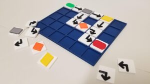
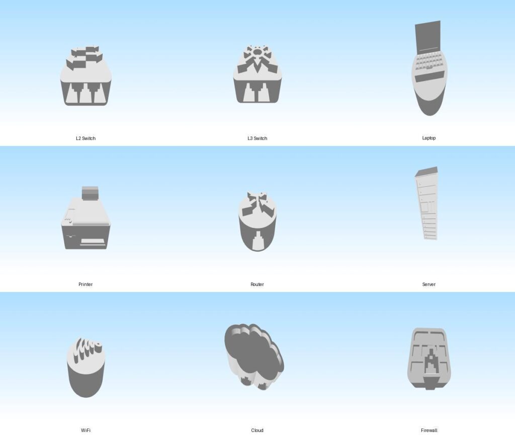
This model represents a tactile computer network diagram composed of multiple 3D network components. The diagram illustrates a typical network structure starting from the internet and progressing through security and network infrastructure devices to end-user devices. The network flow is organized as follows: Cloud → Firewall → Router → Layer 3 Switch → Layer 2 Switch → connected devices such as a server, laptop, printer, and WiFi access point . This structure helps demonstrate how data travels from the internet into a protected network and is then distributed to different devices within a local area network. The model is designed for network education for blind students , allowing learners to explore network topology through touch. Each device includes interfaces for connecting network cables with RJ45 connectors , enabling students to physically build and modify the network structure during hands-on lessons. By connecting the different components, students can better understand concepts such as network hierarchy, traffic flow, switching, routing, and network security .
Printing instructions and tips
Printer type These models are designed for FDM/FFF 3D printers . Recommended orientation Place each model with the flat base on the build plate . This orientation provides the best stability and ensures the network interface openings remain accurate. Layer height Standard quality: 0.2 mm Higher detail: 0.15 mm Lower layer heights improve the tactile surface quality, which can be beneficial for educational use by blind students. Infill Recommended: 15–20% infill Suitable patterns: Grid, Gyroid, or Cubic This provides enough strength while keeping print times reasonable. Supports Most models do not require supports when printed on their base. However, supports may be required for: RJ45 interface openings small overhangs around port areas If supports are used, select “supports from build plate only” to simplify removal. Material Recommended materials: PLA – easiest to print and suitable for classroom environments Avoid very flexible materials, as they may reduce the accuracy of the RJ45 connection interfaces. Print speed Recommended speed: 40–60 mm/s Slower speeds may improve surface quality for tactile exploration. Bed adhesion Normally no brim is required , but a 3–5 mm brim can improve adhesion on smaller printers. Post-processing After printing: Remove any support material from the RJ45 interface openings Check that network cables with RJ45 connectors fit properly Light sanding may help if connectors feel tight Educational use tip These models are designed for tactile network education for blind students . Each device includes interfaces for RJ45 network cables , allowing the components to be physically connected to demonstrate network topology, traffic flow, switching, routing, and network security. Students can assemble the models to create a typical network structure such as: Cloud → Firewall → Router → L3 Switch → L2 Switch → End devices (Server, Laptop, Printer, WiFi Access Point)
Downloads
- Network components Combined (STL)
- Wifi (Network Symbol) (STL)
- Server (Network Symbol) (STL)
- Router (Network Symbol) (STL)
- Laptop (Network Symbol) (STL)
- Printer (Network Symbol) (STL)
- L3Switch (Network Symbol) (STL)
- L2switch (Network Symbol) (STL)
- Cloud-1.stl (STL)
- Firewall-1.stl (STL)
Bundle of all files listed above.